Electrical data
| Electrical interface |
SSI / BISS |
| Output code |
Binary |
| Resolution |
Up to 22 bit |
| Accuracy* |
± 20″ |
| Repeatability |
2.5″ |
| Supply voltage |
+ 5V ± 10% |
| Current consumption (without load) |
< 200 mA |
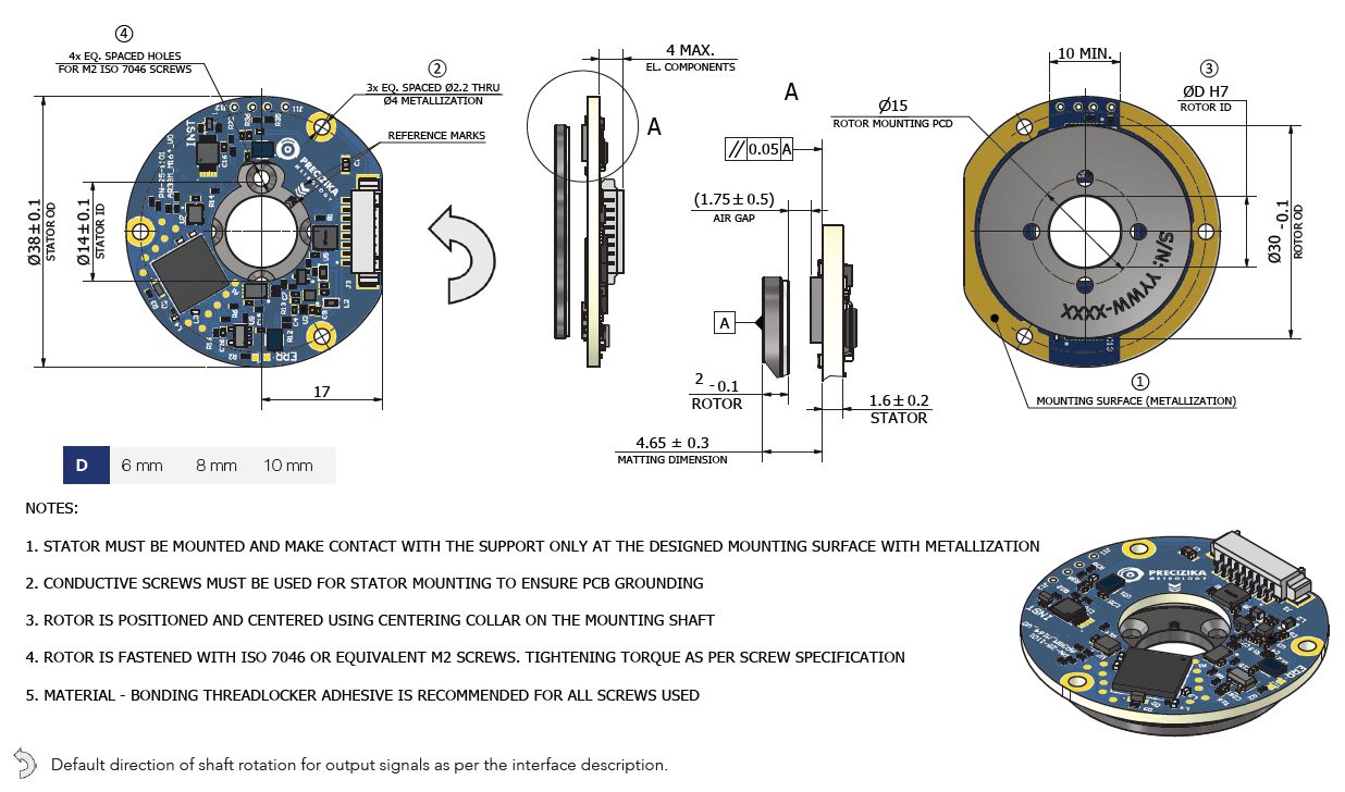
*the overall system accuracy depends on the mechanical mounting conditions, including stator-to-rotor alignment, axial and radial positioning, and rotor eccentricity. Under recommended installation practices, typical system accuracy reaches the specified value.
Note: Deviation from recommended mounting tolerances may lead to increased measurement error.
Zero position setting function
To enhance flexibility in system integration, the encoder includes a dedicated Zero Set input wire, allowing users to define the absolute zero position according to the specific requirements of their application. By activating this input at any desired mechanical position, the encoder reassigns that position as the new absolute zero, ensuring seamless alignment with the machine’s coordinate system. This feature eliminates the need for mechanical repositioning or external software tools, streamlining both installation and commissioning processes. This functionality is especially useful in applications where mechanical reference points vary between builds, or where field recalibration is needed after maintenance or replacement.
Counting direction configuration
To support flexible integration with various mechanical systems, the encoder features an additional input wire that allows users to configure the absolute position counting direction. By toggling this input, the encoder can be set to count position values in either a clockwise (CW) or
counterclockwise (CCW) direction — ensuring compatibility with the specific rotational logic of the application. This feature enables quick adaptation without requiring mechanical changes or firmware reconfiguration, simplifying installation and improving alignment with system control schemes.
Orbisync™ Technology
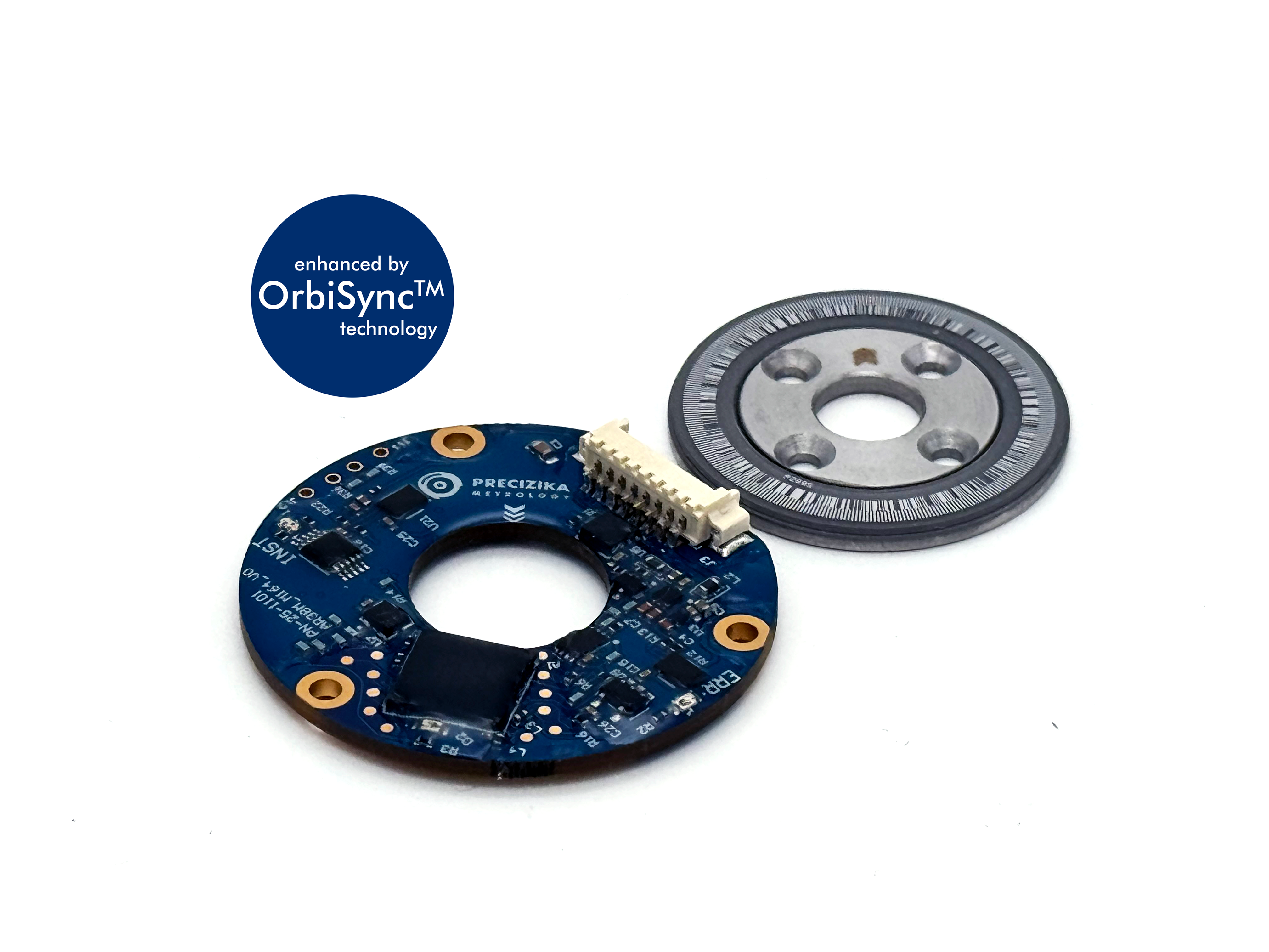
Orbisync™ is a next-generation optical encoder platform developed for high-precision absolute rotary sensing. Leveraging a dual-sensor architecture with built-in intelligence, it continuously calibrates itself to maintain accuracy over time and varying conditions. Advanced onboard processing ensures clean, reliable position data, even in dynamic environments. Its modular design supports both compact open-frame and fully housed configurations, making it a versatile solution for modern motion systems.
Special Features
Precizika Metrology offers exceptional flexibility in our design and manufacturing processes, allowing us to create tailor-made encoders to meet specific customer needs. We can also modify our standard encoders to accommodate different rotor diameters or designs, special wiring configurations, different mechanical interfaces, etc. Additionally, we can incorporate other custom features, such as specialized connectors, couplings, and various accessories, to ensure seamless integration into your application. Furthermore, we can adapt the design and conduct testing for various environmental conditions, including higher ingress protection levels, extended temperature ranges, and resistance to intensive mechanical vibrations or shock.
More information available in the full datasheet.