Mechanical data
| Number of output pulses per revolution | 100 – 108000 |
| Line number on disc (z) | 100; 250; 500; 600; 800; 1000; 1024; 1125; 1250; 1500; 2000; 2500; 3000; 3600; 4000; 5000; 9000; 10800 |
| Maximum shaft speed | 10000 rpm |
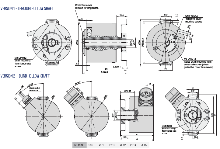
| Maximum shaft load | axial: 0.5 mm radial: 0.05 mm |
| Accuracy (T1-period lines on disc in arc. sec) | ± 0.1T1 arc. sec |
| Starting torque at 20°C | ≤ 0.025 Nm |
| Rotor moment of inertia | < 1.5 x 10⁻⁴ kgm2 |
| Protection (IEC 529) | IP64 |
| Maximum weight without cable | 0.3 kg |
| Operating temperature | -10…+70°C |
| Storage temperature | -30…+80°C |
| Maximum humidity (non-condensing) | 98% |
| Permissible vibration (55 to 2000 Hz) | ≤ 100 m/s² |
| Permissible shock (11 ms) | ≤ 1000 m/s² |