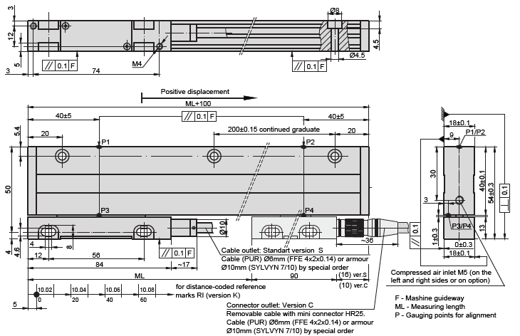
Incremental linear encoder

L18B

Optical linear encoder L18B is able to have the measuring length of up to 3.240 mm, maximum accuracy of ±5 µm to any meter within the ML, and grating periods of ±20 µm, ±40 µm.

Mechanical data

Measuring lengths (ML), mm 70; 120; 170; 220; 270; 320; 370; 420; 470; 520; 620; 720; 820; 920; 1020; 1140; 1240; 1340; 1440; 1540; 1640; 1740; 1840; 1940; 2040; 2140; 2240; 2340; 2440; 2540; 2640; 2740; 2840; 2940; 3040; 3140; 3240
(other intermenate lenghts on request)
Accuracy grades to any meter within the ML (at 20°C) for ML 70 to 2040: ±10; ±5 μm (optional)
for ML 2040 to 3240: ±10 μm
Grating period 20 μm; 40 μm (optional)
Reference marks (RI) standard for ML ≤ 1020 mm: 35 mm from both ends of ML
standard for ML ≥ 1140 mm: 45 mm from both ends of ML
optional: one RI at any location, or two or more RI’s separated by distances of n x 50 mm or distance-coded
Max. traversing speed when interpolation factor is 1,2,5,10: 1 m/s
when interpolation factor is 25: 0.5 m/s
when interpolation factor is 50: 0.4 m/s
Required moving force with sealing lips < 3 N
Protection (IEC 529) with compressed air: IP64
Weight 0.4 kg + 1 kg/m
Operating temperature 0…+50°C
Storage temperature -20…+70°C
Permissible vibration (40 to 2000 Hz) ≤ 30 m/s²
Permissible shock (11 ms) ≤ 100 m/s²

Electrical data

Version L18B-A ∫ µApp L18B-AV ∫ 1 Vpp L18B-F Π TTL
Supply voltage + 5 V ± 5 % + 5 V ± 5 %  + 5 V ± 5 %
Max. supply current (without load) 90 mA 120 mA 120 mA
Light source LED LED LED
Incremental signals Two sinusoidal I1 and I2
Amplitude at 1 kΩ load:
– I1 = 7 – 16 µA
– I2 = 7 – 16 µA
Differential sine +A / -A and +B / -B
Amplitude at 120 kΩ load:
– A = 0.6 – 1.2 V
– B = 0.6 – 1.2 V
Differential square-wave U1 / U1 and U2 / U2. Signal levels at 20 mA load current:
– low (logic “0”) ≤ 0.5 V at Up =± 5V
– high (logic “1”) ≥ 2.4 V at Up =±5V
Reference signal One quasi-triangular I0 peek per revolution. Signal magnitude at 1 kW load:
– I0 = 2 – 8 µA (usable component)
One quasi-triangular +R and its complementary -R per revolution. Signals magnitude at 120 W load:
– R = 0.2 – 0.8 V (usable component
One differential square-wave U0 / U0 per revolution. Signal levels at 20 mA load current:
– low (logic “0”) < 0.5 V at Up =± 5V
– high (logic “1”) > 2.4 V at Up =±5V
Maximum operating frequency 50 kHz 50 kHz 50 kHz, when interpolation factor is 1, 2, 5 ,10
1000 kHz, when interpolation factor is 25, 50
Direction of signals I2 lags I1 for clockwise rotation (viewed from shaft side) + B lags + A in clockwise rotation (viewed from shaft side) U2 lags with U1 in clockwise rotation (viewed from shaft side)
Maximum rise and fall time < 0.5 us
Standard cable length 3 m; without connector 3 m; without connector 3 m; without connector
Maximum cable length 5 m 25 m 25 m

Accessories

Downloads

Order code

L18B – X1 – X2 – X3 – X4 – X5 – X6/X7

Output Signals and Resolution (X1) Measuring Length (X2) Reference Mark (X3) Accuracy (X4) Cable or Connector Outlet (X5) Cable Length (X6) Connector Type (X7)
A – Sinusoidal
AV – Sinusoidal
F01 – TTL 0.1um
F02 – TTL 0.2um
F05 – TTL 0.5 um
F10 – TTL 1.0um
F25 – TTL 2.5 um
F50 – TTL 5.0 um
0070 – 70mm
0520 – 520mm

3240 – 3240mm
N – none IR
S – standard
M – every 50 mm
K – distance coded
Ln/XXX – n`IR with 50-fold steps /XXX distance of the first IR from the begining of ML, mm
05 – ±5 um
10 – ±10um
S – version S (cable outlet)
C – version C (connector outlet)
01 – 1m
02 – 2m
03 – 3m

CP01 – 1m armoured
CP02 – 2m armoured
CP03 – 3m armoured
W – without connector
B12 – round, 12 pins
C9 – round, 9 pins
C12 – round, 12 pins
D9 – flat, 9 pins
D15 – flat, 15 pins
RS10 – round, 10 pins
ONC – round, 10 pins

ORDER EXAMPLE:

  1. L18B-F10-2440-S-05-C-CP03/W

Order form

    Check the "Order code" tab in the product page to see how to know your order code.